Build an internet in VirtualBox
This is a simulation of an in-class hands-on lab exercise. In it, students create 4 small networks. Then the 4 networks
are combined into a single internet. See the "Lab
exercise: build an internet" slides, which blueprint the plan. These
step-by-step instructions accompany them.
For building a localnet physically you would need:
1 switch with power supply
2 laptops
2 cables
optionally, 2 USB NICs to augment a laptop's built-in interface so that it will have 3
of them
Your localnet would consist of the 2 laptops. You or other students would build 4 such 2-computer networks, isolated from each other. Then you would combine them in some way to permit computers in any one network to reach those in the other three networks.
However we will simulate this in VirtualBox.
Your objective
In Figure 4 below, you want to achieve any-to-any connectivity among the PCs, as measured by the ability of any of them to ping and get response from any of the other 3. While the routers will be instrumental in facilitating this, it is not necessary that PCs be able to ping routers, nor routers be able to ping among themselves. The network you will build and the tasks you perform simulate those of a network administrator building a real internetwork. Success depends on software commands on the various machines (ifconfig, route) whose effects are transient. When you turn the machines off, their effects (IP addresses, route table entries) vanish. Therefore it's suggested you try to do this exercise in one sitting; otherwise you have to repeat much of it from scratch. [ addendum: actually VirtualBox has a "Save State" option under each machine's "Close" menu where you can put the current state of the machine in the freezer, shut it down, and take it out of the freezer to resume usage as-it-was later on. ]
Your starting point
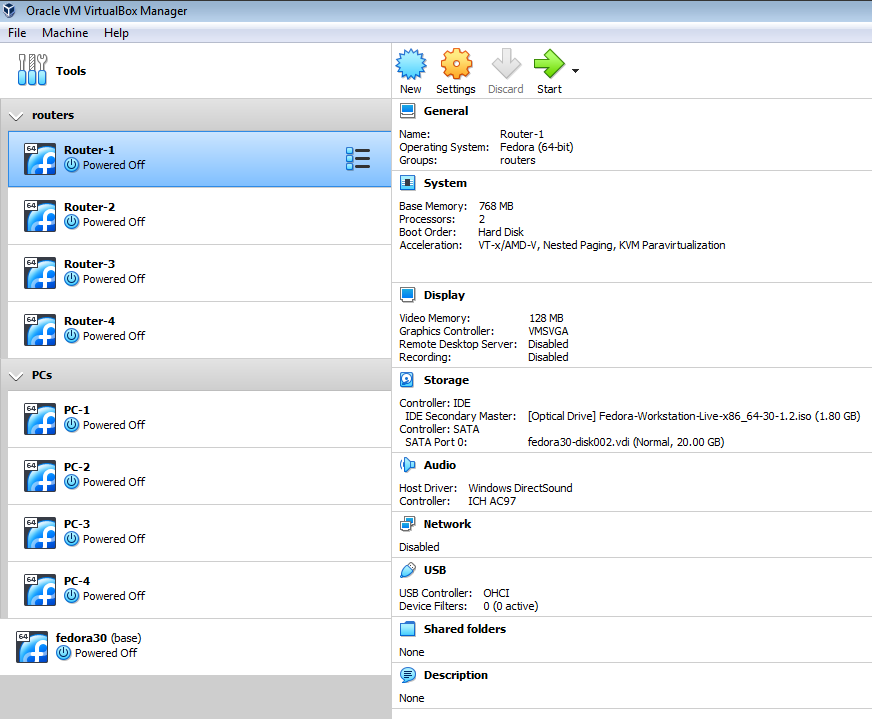
You are provided a base VirtualBox VM named fedora30 (or similar). You are also provided with scripts that create 8 VMs within VirtualBox, by cloning 8 copies of fedora30 (to do it, consult the readme.txt in the zip file yielded by the preceding link).. After populating VirtualBox with these VMs they will appear in the VirtualBox Manager as in Figure 1 (immediately after cloning the two groupings won't be shown, but appear if you exit then re-run the Manager):
FIGURE 1
The VMs all contain a copy of the fedora distribution of linux. However they are
in no way networked. In fact, they don't even have any network interfaces by
which that might be possible (note the "Disabled" notation under
"Network" above). Your main tasks will fall in two areas, first some
work here
within VirtualBox before you ever boot. Then there are other actions within linux inside the VMs after
booting them up. The tasks within VirtualBox are the equivalent of giving the
VMs interfaces and cabling them physically into a prescribed topology. In a
physical setting you would do the same thing, plug things together before you
ever actually boot up. (You may not be used to "giving computers
interfaces" since they come with them built-in. But 1) not these, and 2)
you can certainly give physical computers additional interfaces by plugging in
USB NIC devices for that purpose.) The tasks within linux amount to software
configuration of the machine's networks, applying chosen IP addresses to
interfaces and putting the right entries into their routing tables to achieve
desired connectivity. VirtualBox won't know about IP addresses, just as your
physical computer maker doesn't know about them either. Machine makers-- whether
VirtualBox or Hewlett-Packard-- are ethernet-address-conscious but not
IP-address-aware. The former go into the machines at the factory, the latter
come after the product is long-since shipped out. The manufacturer has no idea
about the IP addresses of its product. So in the VirtualBox Manager
you can look up an adapter's MAC address but there's no IP address to be
found.
Notes on terminology:
MAC address = ethernet address
adapter = NIC = interface
host = computer = machine
Do as indicated below. The specific tasks for you to perform are preceded with an arrow.
Construct the 1st of 4 localnets
Work first with the "PC-1" and "Router-1" VMs. Here is how you would
network them if they were physical:
Hardware, physical, pre-boot:
you would cable PC-1 and Router-1 together into a switch
Software, logical, post-boot:
you would choose a network (netaddr & netmask)
you would choose 2 of its host addresses and apply them to your 2 hosts
you would make sure your 2 hosts can ping each other
In other words, we have both 1) hardware assembly and connection tasks to be done on the lab bench, plus 2) subsequent configuration and software tasks to be done at the command prompt.
Hardware side: Since we don't have an actual lab bench, the VirtualBox Manager program becomes its substitute equivalent. The things you do in the Manager amount to what you would do in placing equipment on the lab bench and organizing it into a desired connected topology using switches and cables, before ever turning the computers on.
Software side: For the command prompt no substitute is needed. When you boot a virtual machine it is as if booting a physical one. You get an actual command prompt. This exercise, beyond the initial hardware setup, is all to be done through the command prompt. It mostly involves choosing and setting IP addresses ("ifconfig" command) and populating route tables to guide packets where you want them to go ("route" command). You don't need a GUI for this, and GUIs are unaffordably memory-expensive. Do not launch the GUI (no "startx" command), because it is unneeded and you will already be taxing your RAM heavily by running multiple VMs simultaneously. If you need to alter the amount of memory per VM, you can do it, when the machine is not running, from within the VirtualBox Manager. Alternatively you could use the command line, specifying which VM you want to change and how much memory you want it to have:
vboxmanage modifyvm <VM> --memory=<amount in MB>
If operations are sluggish, reduce the amount per machine or run fewer machines at a time. Also run fewer other programs generally while doing this exercise.
The physical "cabling together" step is what needs to be done in the VirtualBox manager. The figure below models how to cable two machines together. It creates a LAN named "mynet" that includes/joins 2 computers named "VM1" and "VM2". It is performed, for a given computer, within the computer's VirtualBox network settings. Creating a name there for a VirtualBox "Internal Network" in effect produces a switch. It also cable-connects to it the VM within whose settings you create that name. In settings for other VMs thereafter, you can attach them to that same Internal Network by name, and in effect you thus plug them together into the same switch. An Internal Network name corresponds to a switch and thereby, like with a real one, to a LAN.
FIGURE 2
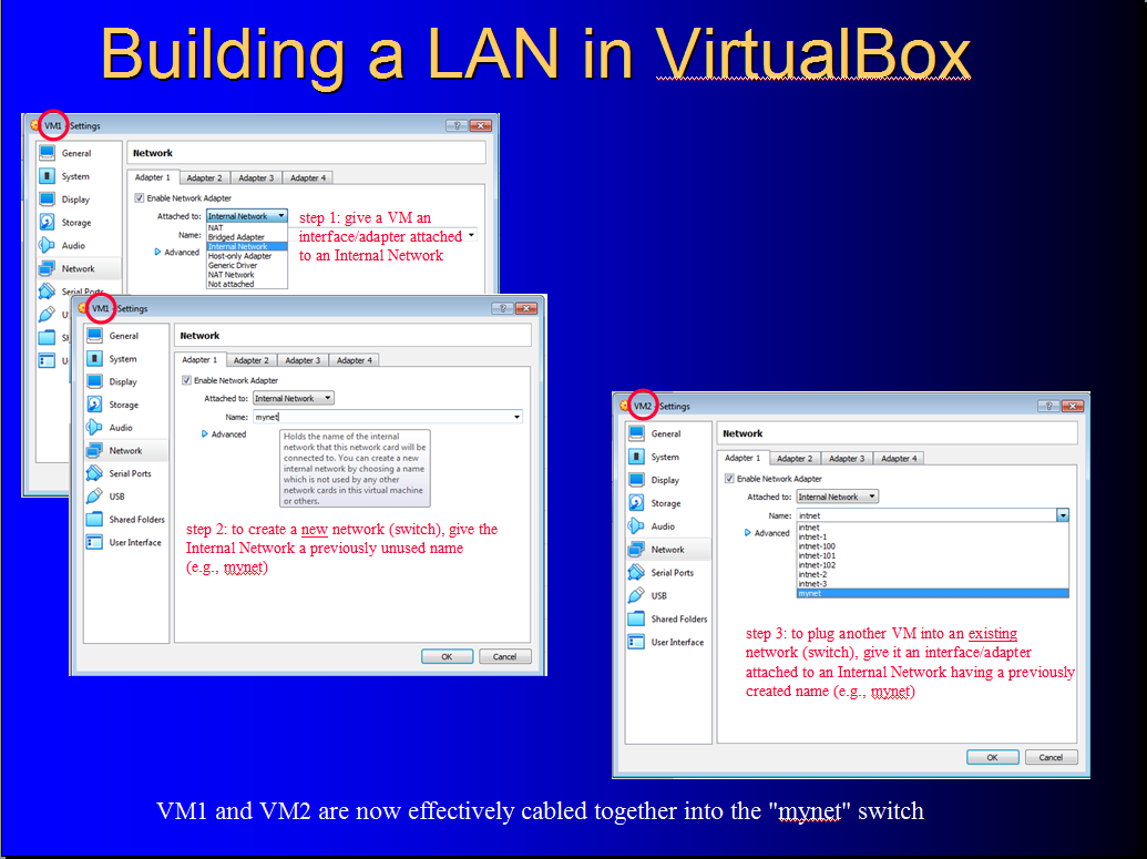
Study the model in Figure 1 carefully, then:
→ follow the model to create a LAN named "N1" that includes/joins PC-1 and Router-1. The adapter to use, for each, is its "Adapter 1".
→ make another network named N2 that joins PC-2 and Router-2. The adapter to use, for each, is its "Adapter 1".
→ make another named N3 that joins PC-3 and Router-3. The adapter to use, for each, is its "Adapter 1".
→ make another named N4 that joins PC-4 and Router-4. The adapter to use, for each, is its "Adapter 1".
You now have this:
FIGURE 3
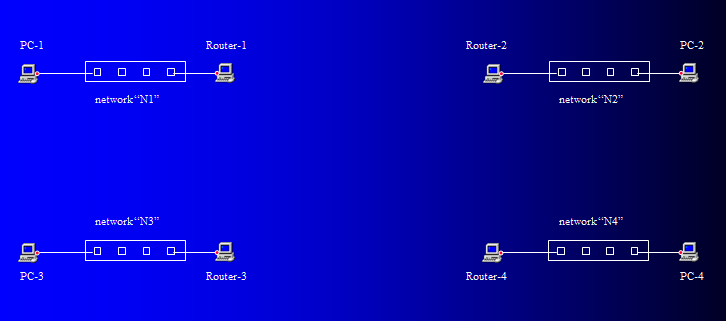
The red dots represent adapters. The diagram omits their names. As far as VirtualBox is concerned, they are all named "Adapter 1" because that's what you used above. VirtualBox Manager's network settings offer you up to 4 adapters. In the exercise below the routers will need 3 interfaces. So now before proceeding to boot, make sure there are 2 more adapters available in each of those 4 machines. Do it as follows:
→ check the "Enable Network Adapter" boxes in both Adapter 2
and Adapter 3 of Router-1
→ check the "Enable Network Adapter" boxes in both Adapter 2
and Adapter 3 of Router-2
→ check the "Enable Network Adapter" boxes in both Adapter 2
and Adapter 3 of Router-3
→ check the "Enable Network Adapter" boxes in both Adapter 2
and Adapter 3 of Router-4
Note that since these are linux machines, linux will give its own names to these adapters when it sees them during bootup. That's no different than with a physical machine. And the names won't be "Adapter 1" for example. Rather, the correspondence between the two naming systems is as follows:
| VirtualBox naming | becomes linux's |
| Adapter 1 | enp0s3 |
| Adapter 2 | enp0s8 |
| Adapter 3 | enp0s9 |
| Adapter 4 | enp0s10 |
Between machines you connected adapters utilizing their VirtualBox names. But once inside linux, when you wish to manipulate them (e.g. give them IP addresses) you will need to use their linux names. If you want to put an IP on Adapter 3, you'll need to put it on "enp0s9" in your ifconfig syntax. This is equivalent to, having physically cable connected a certain interface on one machine to a certain interface on another, bestowing their desired addresses on those interfaces themselves instead of mistakenly on some other interface. Keep the above name correspondences in mind.
Hardware is now in place. Let's boot it up and explore the network administration aspects of internetworking. (Tip: you can economize on screen real estate by making VMs' windows smaller; put each VM in "Scaled Mode." When not in scaled mode a VM window shows a menu. Go to the View menu to find the Scaled Mode setting. Or, the keystroke to toggle scaled mode is probably rightCtrl-C.)
→ Network N1: boot PC-1 and Router-1; log in as root (everything in
this exercise is done as root)
→ choose an IP network (netaddr & netmask) - pick any valid
network you want
→ choose 2 of its host addresses and apply them to the 2 VMs
→ make sure the 2 VMs can ping each other
→ Network N2: boot PC-2 and Router-2; log in as root
→ choose an IP network (netaddr & netmask)
→ choose 2 of its host addresses and apply them to the 2 VMs
→ make sure the 2 VMs can ping each other
→ Network N3: boot PC-3 and Router-3; log in as root
→ choose an IP network (netaddr & netmask)
→ choose 2 of its host addresses and apply them to the 2 VMs
→ make sure the 2 VMs can ping each other
→ Network N4: boot PC-4 and Router-4; log in as root
→ choose an IP network (netaddr & netmask)
→ choose 2 of its host addresses and apply them to the 2 VMs
→ make sure your 2 VMs can ping each other
Construct localnets between routers
For a given localnet you can identify the other 2 localnets that are lateral, not diagonal, to it.
(e.g. for localnet N1, its 2 lateral localnets are N2 and N3 and its diagonal
localnet is N4.)
Repeat the procedure for constructing localnets. You did it 4 times already,
connecting each router to a PC. Now you will connect each router to other routers,
namely its 2 lateral ones. Again, in the VirtualBox Manager on the hardware
side:
→ make another network named N12 that joins Router-1 and Router-2, using their Adapter2's/enp0s8's
→ make another network named N13 that joins Router-1 and Router-3, using their Adapter3's/enp0s9's
→ make another network named N24 that joins Router-2 and Router-4, using their Adapter3's/enp0s9's
→ make another network named N34 that joins Router-3 and Router-4, using their Adapter2's/enp0s8's
For each of these 4 networks in linux on the software side, go to the command prompt in the booted machines to do the following:
Network N12
→ choose an IP network (netaddr & netmask)
→ choose 2 of its host addresses and apply them to the
Adapter2's/enp0s8's of Router-1 and Router-2
→ make sure the 2 member hosts/Router-n's can ping one another
Network N13
→ choose an IP network (netaddr & netmask)
→ choose 2 of its host addresses and apply them to the
Adapter3's/enp0s9's of Router-1 and Router-3
→ make sure the 2 member hosts/Router-n's can ping one another
Network N24
→ choose an IP network (netaddr & netmask)
→ choose 2 of its host addresses and apply them to the
Adapter3's/enp0s9's of Router-2 and Router-4
→ make sure the 2 member hosts/Router-n's can ping one another
Network N34
→ choose an IP network (netaddr & netmask)
→ choose 2 of its host addresses and apply them to the
Adapter2's/enp0s8's of Router-3 and Router-4
→ make sure the 2 member hosts/Router-n's can ping one another
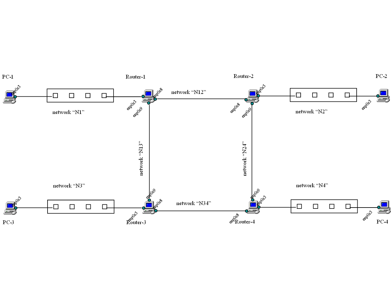
You now have this:

The diagram's 16 interfaces lack the IP addresses you applied to them. But you know what they are. You need to keep track of them. Writing them down on a printed copy of this diagram to serve you as a map might be necessary. Figure 4 is available to you as a topology map you can download and print. There are a lot of numbers here, many moving parts to keep track of. When you choose and apply numbers for a network or an interface, you should write them down here. This will be for your own purposes, and as one of the assigned results for you to submit at the end.
Note that having network N13 between Router-1 and Router-3, for example, affords a possible connecting path between N1 and N3. There is also a connecting path between N1 and N2. What about a connecting path between N1 and N4?
Make route table settings, for lateral integration
On each Router-n
→ add 2 network routes, one to each of its lateral localnets
(gatewayed through those lateral networks' routers)
as example on Router-1: route add -net <N2's netaddr/netmask
spec> gw <Router-2's enp0s8 IP address>, and
route add -net <N3's netaddr/netmask spec> gw <Router-3's enp0s9's IP
address>
(note: if you ever need to back out of a route table entry, the
"route" command accepts "del" in place of "add" to
do that, so long as the rest of the command is preserved)
On each PC-n, non-router machine
→ add a default route to its LAN's Router-n
as example on PC-1: route add default gw <Router-1's enp0s3's IP
address>
At this point we must attend to a detail. The network software that comes with
most regular operating systems is configured to never forward packets. That is,
to never move an incoming packet from the NIC on which it entered to any other NIC.
It's just the opposite to those little computers that are sold as home (or
other) routers. But if you wish to use a stock, consumer operating system like
fedora linux for a router you have to change the configuration. In effect, there
is a closed valve between interfaces and you need to open it. In Windows there's
a check box. In linux, on each of the routers, do this:
On Router-1
→ echo 1 > /proc/sys/net/ipv4/ip_forward
On Router-2
→ echo 1 > /proc/sys/net/ipv4/ip_forward
On Router-3
→ echo 1 > /proc/sys/net/ipv4/ip_forward
On Router-4
→ echo 1 > /proc/sys/net/ipv4/ip_forward
Make sure each PC-n can now successfully ping 4 VMs: 1) the "Router-n"'s of both its lateral networks, and 2) the "PC-n" in both its lateral networks
If something doesn't work, tcpdump is your diagnostic friend! For example if on PC-1 you try to ping PC-2 but get no response, the bottleneck that's blocking could be in PC-1 itself, in Router-1, in Router-2, or in PC-2. Maybe the request never makes it to the target; maybe the reply never makes it back. tcpdump can pinpoint the blockage. Use it, for example, on PC-1 as "tcpdump -nnti enp0s3" to see if "echo request" packets are seen departing. If so, then move to Router-1 and use "tcpdump -nnti enp0s3" to see if they are arriving, or if so "tcpdump -nnti enp0s8" to see if they are departing, and so forth down the line till you fail to see an expected request or, in the other direction, reply. Then, you know which computer isn't doing its job and can try to figure out why.
Once you succeed, every PC can talk to their lateral PC friends. But nobody can reach their diagonal ones yet.
Make route table settings, for diagonal integration
On each Router-n router
→ add a network route, that goes to its diagonal localnet
as example on Router-1: route add -net <N4's netaddr/netmask
spec> gw <somebody's IP address, 2 possibilities here, figure it out and
pick one>
On the PC-n's
do nothing
make sure each Router-n router machine can ping the PC-n non-router in its diagonal
network
make sure each PC-n non-router machine can ping the PC-n non-router in its diagonal
network
At this point you are finished. This or other VirtualBox networks could be further explored to learn about things like network address translation, port forwarding, persistent addressing, or different topologies. If you wish, keep your VirtualBox installation for such future purposes and further learning.
What to turn in
Submit three things, in a single zip file.
First, your annotated topology map. On it, clearly make 24 written entries-- 8 network specifications (netaddr/netmask) and 16 IP addresses. Do it in pencil or pen and scan it to a file, or if you have electronic means annotate the file that way.
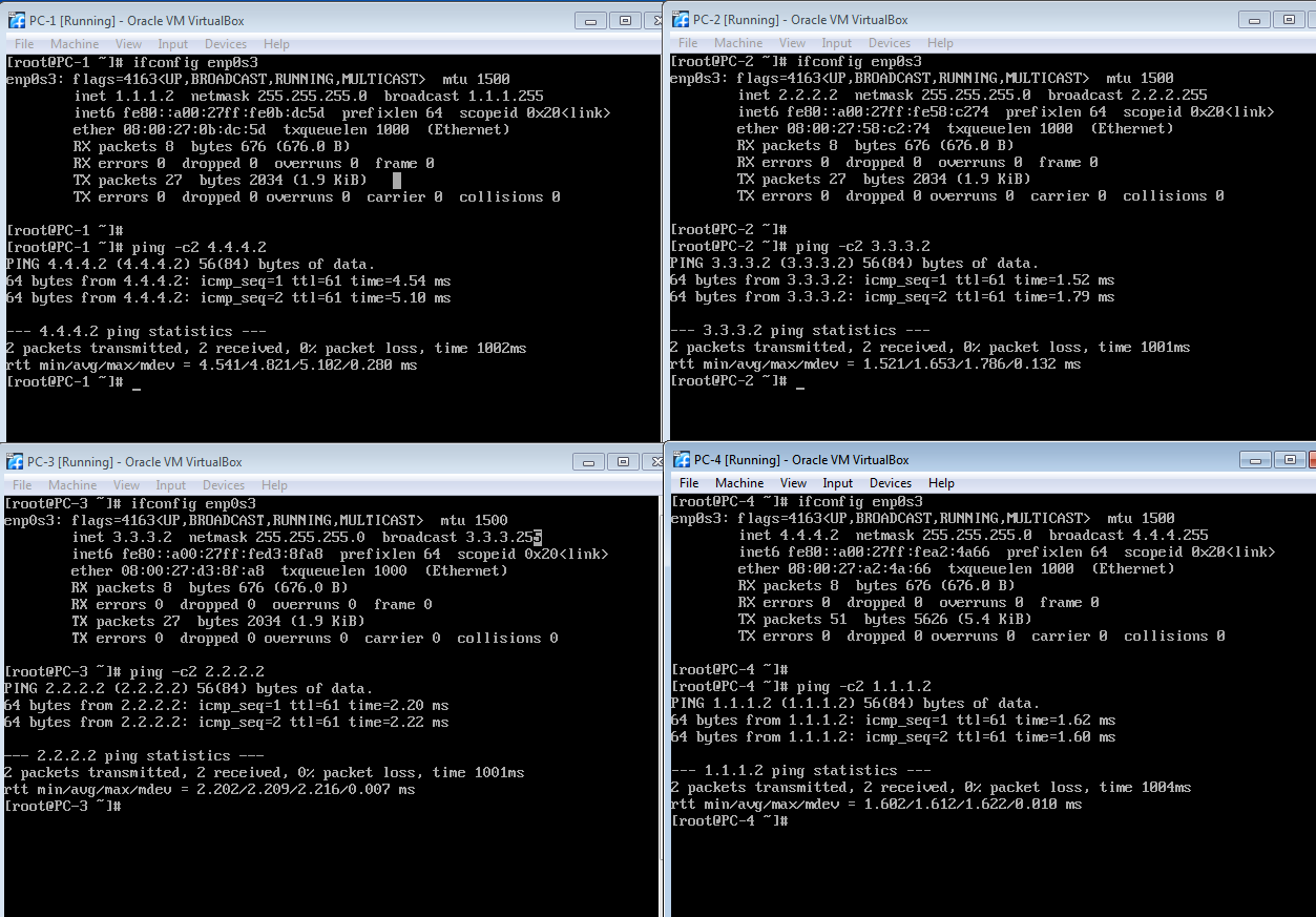
Second, a screen shot showing the tiled screens of your 4 PCs. Each should show that PC's IP addresses, and show it pinging its diagonal counterpart. Here is my screenshot. Yours should be just like mine, though you will presumably have different numbers than those I chose.
Third, a screen shot showing the tiled screens of your 4 Routers. Each should show that router's route table. Here is my screenshot. Yours should be just like mine, though you will presumably have different numbers than those I chose.
Put your 3 files into a zip file named "internetworking.zip"
and place it in your assignments directory on the remote Unix server.